
Views: 0 Author: Site Editor Publish Time: 2026-09-13 Origin: Site


Transporting heavy project cargo presents a strict engineering challenge for maritime logistics. Relying solely on gross tonnage metrics to plan shipments often results in catastrophic structural failure. Miscalculating the difference between global deadweight and localized deck strength leads to severe consequences. You face compliance violations, operational delays during Ro-Ro loading, and permanent vessel damage. We see operators punch holes through deck plates because they confused total capacity with point load limits.
This guide deconstructs the engineering variables that dictate lct vessel deck capacity. We provide procurement and logistics teams with a rigorous framework for evaluating vessel specifications against actual cargo profiles. You will learn how to separate theoretical tonnage from practical deck limitations. We cover everything from ramp tolerances to ballast management. This ensures your next heavy-lift operation remains safe, compliant, and structurally sound from port to port.
Evaluating deck capacity requires strict baseline success criteria. The vessel must physically support the cargo mass without compromising hull integrity or stability. Planners must look far beyond basic dimensions. You need to understand the structural limits of the steel beneath the cargo. When you load a 150-ton transformer, the deck plating and under-deck framing take the immediate stress. If that framing yields, the entire voyage is compromised. We evaluate capacity by looking at how the vessel handles weight distribution across its entire structural grid.
Global Deadweight (DWT) defines the total weight a vessel can safely carry. This metric includes cargo, fuel, fresh water, ballast, and crew. Loading to maximum DWT brings the vessel down to its minimum sailing draft. However, DWT only tells part of the story. It is a macro-level metric used primarily for overall voyage planning and regulatory compliance.
DWT contrasts sharply with deck load capacity. Deck capacity dictates exactly where and how weight distributes across the cargo deck. You might have 5,000 tons of available DWT. If your deck can only support 5 tons per square meter, dense heavy cargo will punch through the steel plating. We frequently see operators assume a high DWT means they can load anything. This assumption destroys decks and leads to costly shipyard repairs.
Physical hold dimensions present a similar trap. Fitting a specific number of 20' 1CC containers (TEU) is a matter of geometry. The structural capacity must actually support that global deck load. A deck might fit fifty containers physically. It may only possess the structural framing to support thirty fully loaded units safely. You must calculate the weight of the cargo, not just its footprint. Stacking heavy containers requires verifying the point loads at the corner castings against the deck's structural intersections.
Distributed load measures uniform weight across a broad area. Engineers calculate this in tons per square meter (t/m²). Standard containers, bulk materials, and palletized goods generate distributed loads. The vessel's longitudinal framing easily absorbs these uniform pressures. The load spreads evenly across multiple transverse webs and longitudinal bulkheads, allowing the hull girder to flex naturally during transit.
Point loads present a much higher risk profile. Heavy tracked machinery, specialized project cargo skids, and crane outriggers generate massive concentrated loads. These loads apply intense pressure to isolated deck sections. A crawler crane might weigh 100 tons. If that weight rests on four small outrigger pads, the localized pressure far exceeds standard t/m² limits. Point loads demand specialized deck reinforcements to prevent localized buckling.
| Cargo Type | Load Classification | Typical Pressure Profile | Structural Impact on Deck |
|---|---|---|---|
| Standard 20ft Containers (TEU) | Distributed Load | 2 to 4 t/m² | Uniform stress absorbed by standard longitudinal framing. |
| Bulk Sand or Gravel | Distributed Load | 3 to 5 t/m² | Even weight distribution; requires standard plate thickness. |
| Crawler Crane (100t) | Point Load | 15 to 25 t/m² (under tracks) | High risk of localized plate deformation; requires dunnage. |
| Heavy Transformer on Skids | Point Load | 20+ t/m² (under skids) | Extreme concentrated stress; demands under-deck pillar reinforcement. |
Maximum safe loading parameters depend on physical vessel design and environmental factors. You must evaluate both dimensions to ensure operational safety. Ignoring the environment while focusing only on the steel leads to accidents during loading. A strong deck cannot compensate for a weak ramp or poor draft conditions.
Under-deck framing dictates maximum allowable t/m². Longitudinal bulkheads, transverse webs, and heavy plate thickness form the structural backbone. Closely spaced frames increase deck rigidity. Thicker steel plating resists point-load deformation. A deck built with 16mm steel behaves very differently than one built with 22mm steel under a heavy excavator. Reviewing detailed LCT vessel technical specifications reveals these hidden structural capabilities. You must look at the shipyard drawings to see the spacing of the transverse frames.
Ballast tank configurations heavily influence deck strength and stability. Forepeak tanks and double bottom tanks provide necessary buoyancy control. Their specific volumetric capacities allow the crew to offset heavy deck loads. Pumping water into double bottom tanks lowers the center of gravity. This stabilizes the vessel when loading top-heavy project cargo. Without adequate ballast capacity, a vessel with a strong deck might still capsize from poor stability during the loading sequence.
The distinctive bow ramp system acts as a primary bottleneck for deck capacity. The ramp's safe working load (SWL) must exceed the heaviest single piece of rolling cargo. If your deck holds 1,000 tons, but the ramp SWL is 50 tons, you cannot load a 60-ton excavator via Ro-Ro. The ramp hinges bear massive shear forces during loading, and exceeding the SWL will shear the hinge pins instantly.
Shoreline gradients and tidal variations multiply ramp stress. A steep shoreline angle forces the ramp hinges to bear unnatural shear forces. Dynamic loads introduce further complications. Ship-to-ship cargo transfers cause vessels to roll independently. This movement creates sudden, severe stress spikes on both the ramp and the forward deck plating.
To manage ramp limits, crews must execute specific checks before loading:
Regulatory frameworks dictate legal loading limits. The load line length plays a central role here. Regulators define this as 96 percent of the total waterline length, or the length from the forward perpendicular (FP) to the axis of the rudder stock. The greater value applies. This measurement determines the vessel's assigned freeboard and maximum legal draft. You cannot legally submerge the load line mark, regardless of how much physical space remains on the deck.
Port draft restrictions often supersede theoretical deck capacity. You might have the deck strength and the DWT to carry 3,000 tons. If the destination port only has a 3-meter draft, you cannot load to maximum capacity. Follow this calculation methodology when facing shallow ports:
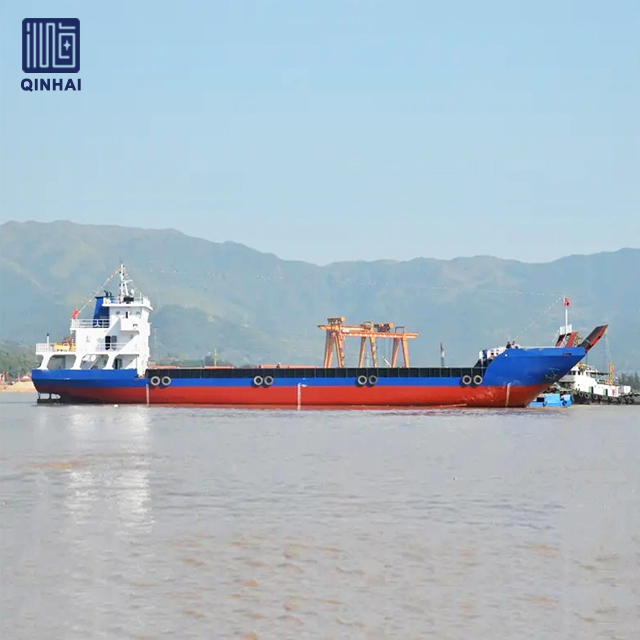
Deck capacity scales dynamically with project requirements. Comparing different vessel sizes illustrates how structural engineering adapts to cargo profiles. A small barge operates under entirely different structural rules than a massive heavy-lift vessel. You must match the vessel class to the specific demands of your cargo footprint.
A standard 1000 DWT LCT cargo barge optimizes for shallow-water logistics. These vessels navigate riverine and inter-island routes effectively. They feature standard deck strengths, typically ranging from 5 to 7 t/m². This capacity easily handles palletized goods, standard containers, and light commercial vehicles. The under-deck framing relies on standard longitudinal spacing without the need for heavy pillar reinforcements. They are workhorses for basic supply runs.
Scaling up to a 5000 DWT LCT cargo barge changes the operational dynamic. Hold dimensions increase significantly. Engineers upgrade the under-deck framing to provide higher point-load tolerances, often pushing 10 to 15 t/m². This allows the safe transport of mid-sized construction equipment like bulldozers and graders. Enhanced ballast capacities improve minimum sailing stability, counteracting the higher center of gravity from heavier deck loads. The ramp systems on these vessels also feature reinforced hinges to handle heavier Ro-Ro traffic.
Complex project cargo demands extreme structural integrity. A 20000 DWT LCT vessel with crane represents the apex of specialized deck engineering. The structural requirements shift from uniform load distribution to managing massive localized forces. These vessels operate in offshore environments and handle massive industrial modules, wind turbine components, and heavy mining infrastructure.
Engineers install heavy localized deck reinforcements beneath the crane pedestal. These foundations transfer the crane's dynamic lifting forces directly into the hull girder. Integrating heavy-lift operations (Lo-Lo) with traditional Ro-Ro capabilities requires complex stability calculations. Crane slewing motions shift the vessel's center of gravity rapidly. The global deck load must account for both the static cargo weight and the dynamic forces generated during crane operations. The deck plating in the primary cargo zone often exceeds 25mm in thickness, supported by massive under-deck pillars.
| Vessel Class | Typical Deck Strength | Primary Operational Profile | Key Structural Features |
|---|---|---|---|
| 1000 DWT LCT | 5 - 7 t/m² | Riverine, inter-island, shallow-water logistics | Standard longitudinal framing, basic bow ramp |
| 5000 DWT LCT | 10 - 15 t/m² | Regional transport, mid-sized construction equipment | Enhanced double bottom tanks, reinforced ramp hinges |
| 20000 DWT LCT | 20+ t/m² (Localized) | Heavy lift, complex project cargo, Lo-Lo operations | Massive under-deck pillars, crane pedestal foundations |
Poor cargo planning leads to structural damage and regulatory detention. Mitigating these risks requires strict adherence to engineering limits. You cannot guess weights or assume deck strength based on visual inspections. Every load must be calculated and verified against the vessel's approved stability booklet.
Steel-tracked excavators and crawler cranes pose severe risks to deck plates. The steel tracks create massive point loads. Driving this equipment directly onto an unreinforced deck often causes permanent plate deformation. The steel yields under the concentrated pressure. We see corrugated deck plates constantly because crews failed to distribute the load. Let us look at a practical calculation. A 120-ton crawler crane with two tracks, each 5 meters long and 0.8 meters wide, has a total contact area of 8 square meters. Dividing 120 tons by 8 square meters yields a point load of 15 t/m². If the deck is rated for 10 t/m², the steel will buckle.
Mitigation requires distributing the load footprint. Crews must utilize heavy timber dunnage or steel load-spreading mats. Hardwood timbers like Azobé or Ekki are preferred because they do not crush under extreme point loads. These materials spread the machine's weight over a larger surface area, converting a dangerous point load into a manageable distributed load. Always verify the exact footprint of the cargo against the vessel's technical drawings before loading commences.
Follow these steps for loading tracked equipment:
Asymmetric loading introduces severe capsizing risks. Placing heavy project cargo off-center generates dangerous shear forces across the hull girder. The vessel will list, reducing its righting lever and compromising overall stability. A listing vessel also places uneven stress on the bow ramp during discharge operations, which can cause the ramp to twist and jam.
Real-time ballast management prevents these failures. Crews utilize specific forepeak and double bottom tank capacities to counteract asymmetric loads. These tanks often hold hundreds of cubic meters of water. Pumping ballast to the opposite side of the heavy cargo maintains an even keel. Proper ballast management ensures the vessel meets minimum sailing drafts while minimizing stress on the hull structure. You must calculate the ballast plan before the first piece of cargo crosses the ramp. Adjusting ballast reactively during a heavy lift is highly dangerous.
Procurement teams must evaluate suppliers based on engineering flexibility. Long-term asset value depends on matching vessel capabilities to specific cargo profiles. Buying a generic vessel for specialized work guarantees failure. You need a shipyard that understands the physical realities of heavy-lift operations.
Off-the-shelf vessels frequently fail to meet rigorous point-load requirements. Standard designs optimize for general cargo, not specialized heavy lift modules. Purchasing a standard vessel for complex project cargo guarantees operational bottlenecks. You will spend thousands on temporary dunnage for every voyage, eating into your operational margins.
Selecting a capable custom LCT vessel supplier eliminates this risk. Look for shipyards with in-house naval architecture teams. They must provide transparent structural analysis, including Finite Element Analysis (FEA) of the cargo deck. FEA models the deck grid, simulates the exact footprint of the cargo, and applies virtual gravity and dynamic wave forces. The software highlights stress concentrations, allowing naval architects to add steel exactly where needed. Ensure the supplier guarantees classification society compliance, preferably working with IACS members to certify the custom deck reinforcements.
Standard builds offer faster delivery times and lower initial costs. However, they limit your operational scope. Purpose-built modifications require a higher upfront investment but deliver superior long-term ROI. Custom reinforced decks allow you to bid on lucrative heavy-lift contracts that standard vessels cannot execute safely. A reinforced deck means faster loading times and less reliance on expensive external load-spreading equipment.
When evaluating these trade-offs, submit detailed cargo profiles during your initial LCT vessel price inquiry. Provide the shipyard with exact dimensions, weights, and point-load requirements of your heaviest equipment. This ensures the quoted vessel actually meets your operational reality. Do not accept a generic quote without a structural capability guarantee. The shipyard must prove their design can handle your specific t/m² requirements.
A: Global DWT measures the total weight a vessel can carry, including cargo, fuel, and water, to reach its minimum sailing draft. Deck load capacity measures how much weight specific deck sections can support, usually calculated in tons per square meter (t/m²).
A: Divide the total weight of the machinery by the actual contact area of its steel tracks. This yields the concentrated pressure applied to the deck. Compare this figure against the vessel's maximum allowable point load specifications.
A: The cargo deck might support 1,000 tons, but rolling cargo must cross the bow ramp first. If the ramp's safe working load (SWL) is only 50 tons, you cannot load any single piece of equipment exceeding that weight.
A: Load line length determines the vessel's assigned freeboard and maximum legal draft. It dictates the absolute maximum weight you can load legally, regardless of the physical space available on the cargo deck.
A: Generally, no. Crane outriggers generate massive concentrated point loads. Standard decks require heavy timber dunnage or steel load-spreading mats to distribute this pressure and prevent the deck plates from buckling.
A: Ballast tanks control buoyancy and stability. Pumping water into double bottom or forepeak tanks lowers the center of gravity, counteracts asymmetric heavy loads, and maintains an even keel during complex cargo operations.


